Wednesday, March 23, 2011

SCADA/REMOTE VIEWING CONNECTION WITH S7-1200 ON PROFINET!
Call us for live demo!


Notes

* Restrictions,
- Only tags in the data block DB1 of your S7-1200 PLC can be accessed because the S7-200 only had one data block.
- DB1 in your S7-1200 PLC needs to be non-symbolic. Please uncheck the checkbox "Symbolic access only" when creating your DB1.

** SPAN APPROVED SCADA SYSTEM

# Artist illustrations for marketing purpose only, actual supplied products may differ from this leaflet/proposals/brochures

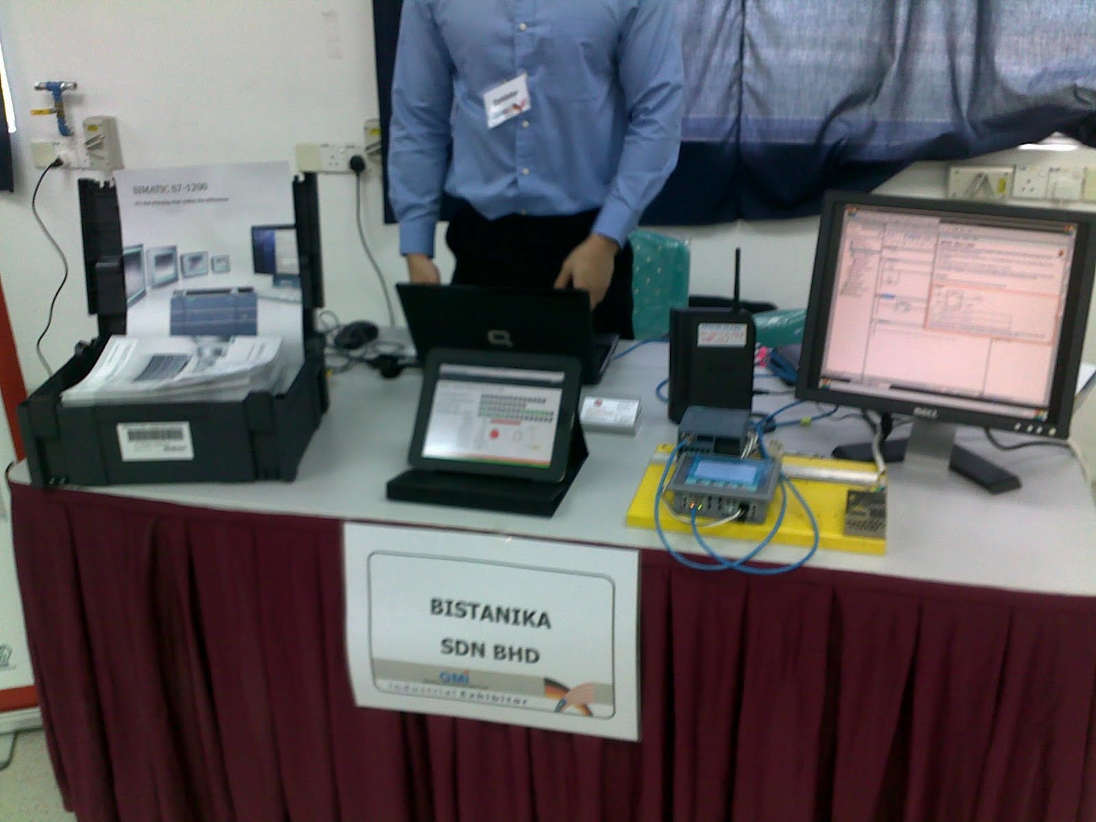
S7-1200 EXHIBTION AT GMI OPEN DAY ON 2011 MAC 19


Wednesday, March 9, 2011

SCADA/REMOTE VIEWING CONNECTION WITH S7-1200 ON PROFINET!
Call us for live demo!


Notes

* Restrictions,
- Only tags in the data block DB1 of your S7-1200 PLC can be accessed because the S7-200 only had one data block.
- DB1 in your S7-1200 PLC needs to be non-symbolic. Please uncheck the checkbox "Symbolic access only" when creating your DB1.

** SPAN APPROVED SCADA SYSTEM

# Artist illustrations for marketing purpose only, actual supplied products may differ from this leaflet/proposals/brochures

S7-1200 Product News Nov 2010 Issue
*Email us if you require full version


Thursday, March 3, 2011

Week 4: Decentralized positioning of a SINAMICS S110 with S7-1200 via USS-Protocol (CE-X9)

Automation task:
A synchronous motor that is connected with a servo drive type SINAMICS S110 is to be positioned via the CM1241 (RS485) communication module of a S7-1200 controller (CPU1214C). Communication between controller and servo drive will be performed by USS protocol. Operation and visualization takes place via a KTP600 touch panel which is to be connected via an Ethernet connection to the S7-1200 controller. STEP 7 Basic V10.5 is used as configuration tool for the control program and the HMI. The servo drive is configured using the STARTER startup tool. The task consists of the following scenarios:

  • moving the motor in jog mode
  • referencing
  • absolute and relative positioning
  • moving the motor according to defined motion profiles
In order to position the motor, setpoint position and the setpoint velocity have to be transferred via the USS protocol to SINAMICS S110, as well as various command bits. SINAMICS S110 will then independently control the positioning or moving of the motor. The SINAMICS S110 will give a feedback to the controller on the various status bits, the actual position the actual velocity and also of error messages.


Figure 01

Startup Code:
For the startup we offer you software examples with test code and test parameters as download. These software examples support you in the first steps and tests of the configuration examples. They enable a quick test of hardware and software interfaces of the products described in the configuration example


Need to know more?

Check it out at Siemens IA/DT Support

*All information are extracted from Siemens IA/DT Support Website

Thursday, February 24, 2011

Week 3: Ethernet Communication Data Exchange between S7-1200 and S7-1200

Automation task:
Data exchange (e.g. for time synchronization) shall be enabled between an S7 1200 master controller and several S7-1200 slave controllers.


Figure 01

The S7-1200 compact controllers are configured using the STEP 7 Basic V10.5 SP2 programming user interface.

Automation solution:
For data exchange via Ethernet the SIMATIC S7-1200 provides the open TCP/IP communication with the T communication block:

  • TCON, TSEND, TRCV and TDISCON (with explicit execution of the connecting and disconnecting process) and

  • TSEND_C and TRCV_C (with integrated connecting and disconnecting process).

The following protocols are supported by the T communication blocks:

  • TCP native

  • ISO-on-TCP (dynamic data length transmission)

On the master as well as the slave side the communication blocks with explicit execution of the connecting and disconnecting process are selected:

  • TCON for establishing the connection

  • TSEND for sending the data

  • TRCV for receiving the data

  • TDISCON for disconnecting

The selected protocol is “ISO-on-TCP”. In the OSI model the “ISO-on-TCP” protocol is added to the TCP protocol and provides the advantage of a message-orientated approach, which is especially helpful for the communication between SIMATIC systems.
For the connection configuration in STEP 7 Basic V10.5 the respective connection parameter is identified via the IP address. For a configured connection a connection resource is reserved and the connection parameters are stored in a connection data block. The IP address of the partner is also stored here.
The maximum number for the open T communication is limited to a maximum of 8 simultaneous connections.
Changing the IP addresses in the connection data block enables data exchange between more than 8 different communication partners via the same connection resource.


Figure 02

Master and slaves have one send and one receive data block each (Send_DB and Receive_DB). The master sends a TCP/IP connection request to the first slave via the TCON block. To acknowledge the established connection the partner also executes the TCON block. For a synchronization request the master reads the system time and sends it to the slave via the TSEND communication block together with the user data. With the TRCV receive block the slave receives the data in the Receive_DB data block. The slave synchronizes its system time with the received clock time of the master. Then slave 1 sends its user data to the master via the TSEND block. The user data of slave 1 are stored on the master side via the TRCV block at the given location in the receive data block. Then the master disconnects from slave 1 via the TDISCON block. This procedure is repeated with the subsequent slaves. After the data exchange between master and the last slave the master starts the data exchange with slave 1. On the slave side a once established connection remains reserved. So TCON must only be called for initialization.


Need to know more?

Check it out at Siemens IA/DT Support

*All information are extracted from Siemens IA/DT Support Website